
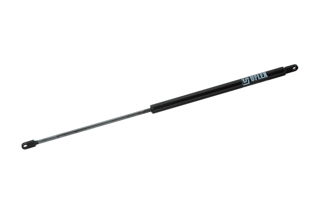
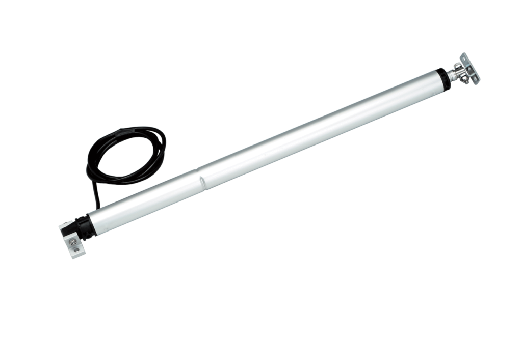
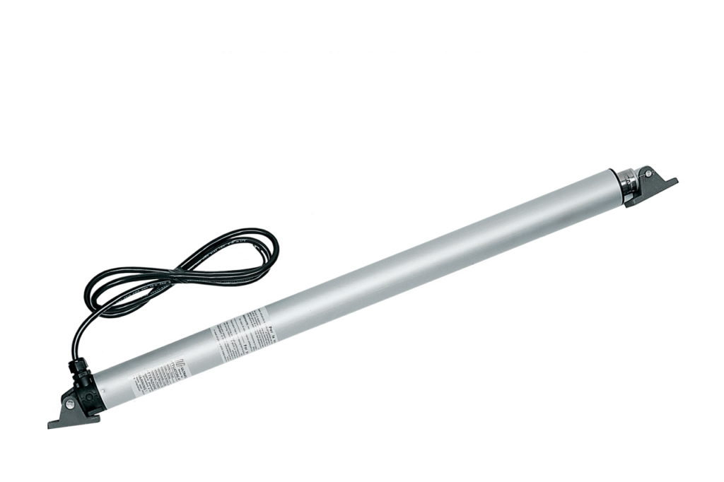
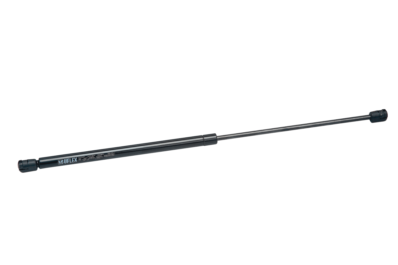
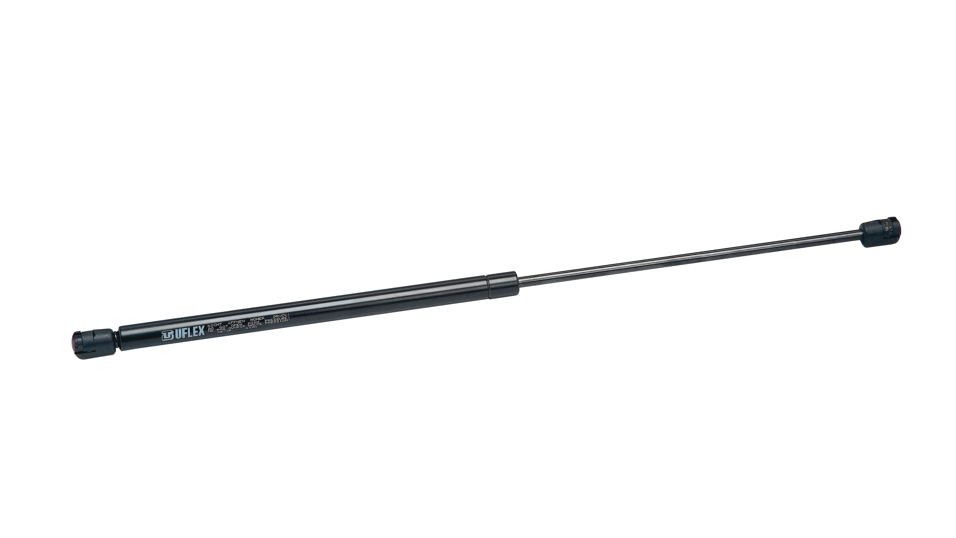
Uflex Black painted gas springs UB series
Nitro-protected steel rod and marine corrosion resistant black painted cylinder. Thermoplastic ball bearing end fittings to be threaded on.
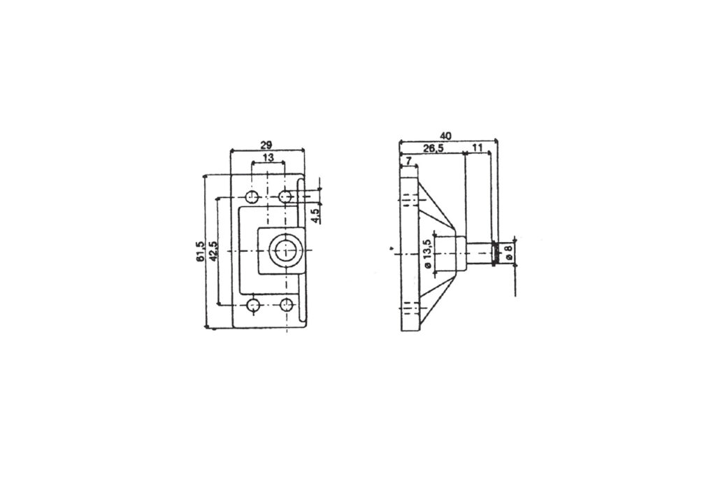
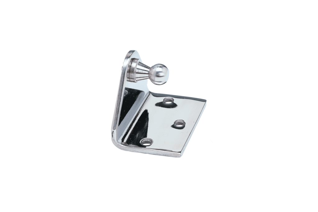
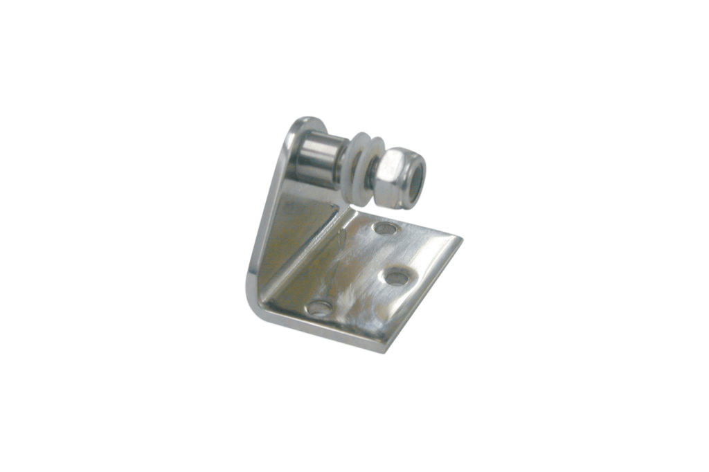
End fittings
Kit KB01: 2 ball bearing end fittings to be threaded on the gas spring – to be ordered separately
Uflex Gas springs
Gas springs are pneumatic force accumulators mainly used to lift, hold open and smoothly lower hatches, covers, lids and doors.
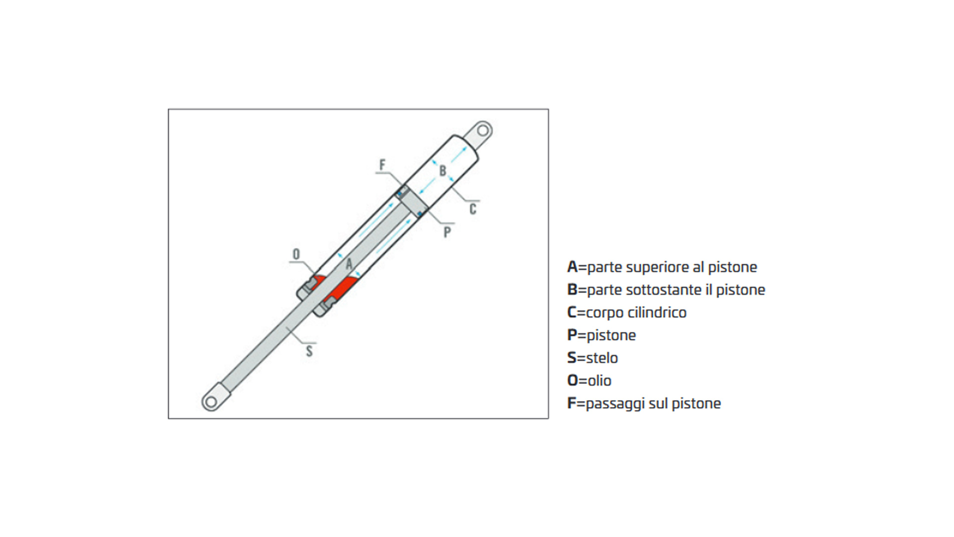
A gas spring, not equipped with a lock device, functions as follows: the pressure of the compressed nitrogen gas contained in a tube provides the extension force of the spring as the result of the difference between the internal tube pressure and the atmospheric pressure. The gas flows from the highest to the lowest pressure compartment of the tube through a self-cleaning orifice in the piston rod causing the spring rod to telescope out of the pressure tube.
Each tube incorporates a small quantity of oil that provides lubrication of the seals and of the piston rod and, at the same time, a damping medium to control the opening speed of the cover or hatch.

A=upper part
B=below the piston
C=cylinder
P=piston
S=piston rod
O=oil
F=channels
UFLEX gas springs are supplied in OEM or in Aftermarket packaging. Please specify when ordering.
INSTALLATION

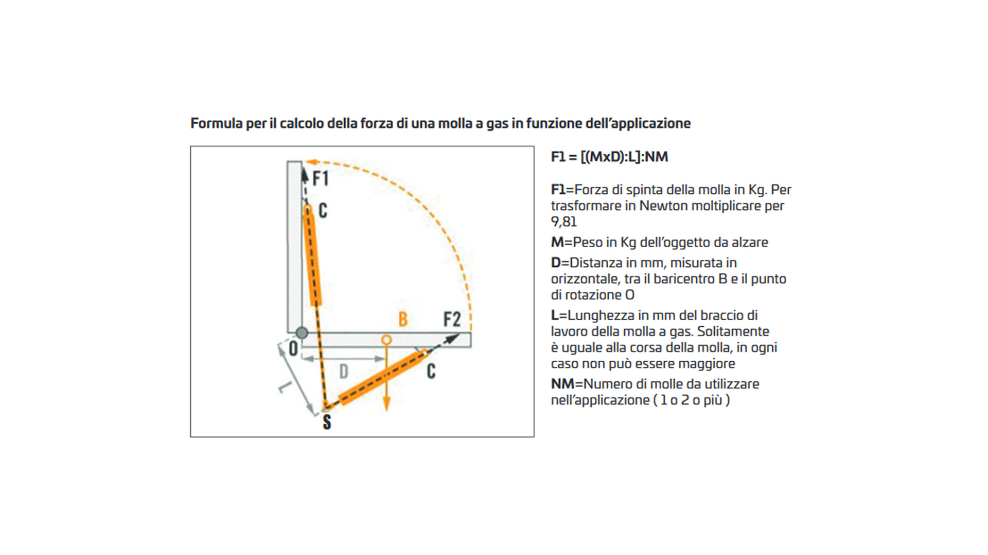
Formula to calculate the force of a gas spring
F1 = [(MxD):L]:NM
F1=Force of the spring which opposes the weight of the object to be moved; in this case, F1 expressed in kg and have to be transformed in Newton multiplying the value obtained by 9.81.
M=Weight in kg of the object to be lifted.
D=Distance in mm measured horizontally between the center of gravity B and the point of rotation O.
L=Length in mm of the gas spring working arm; most of the time it is equal to the stroke of the gas spring and in case cannot be greater.
NM=Number of gas springs to be used in the application (1, 2 or more).
WARNINGS
• The rod surface should be protected against physical or chemical damages.
• Lateral loads should be carefully avoided.
• Attachment pivots should be well aligned.
• Springs should be mounted according to previous installation instructions ensuring correct orientation.
• Tensile forces exceeding the output force as indicated for each single spring should be avoided.
• Working temperature – 30° C and + 80°C.
