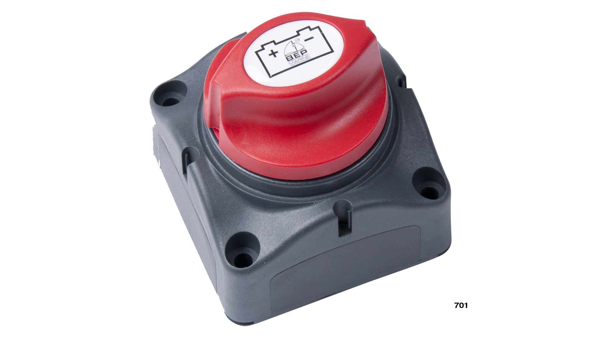
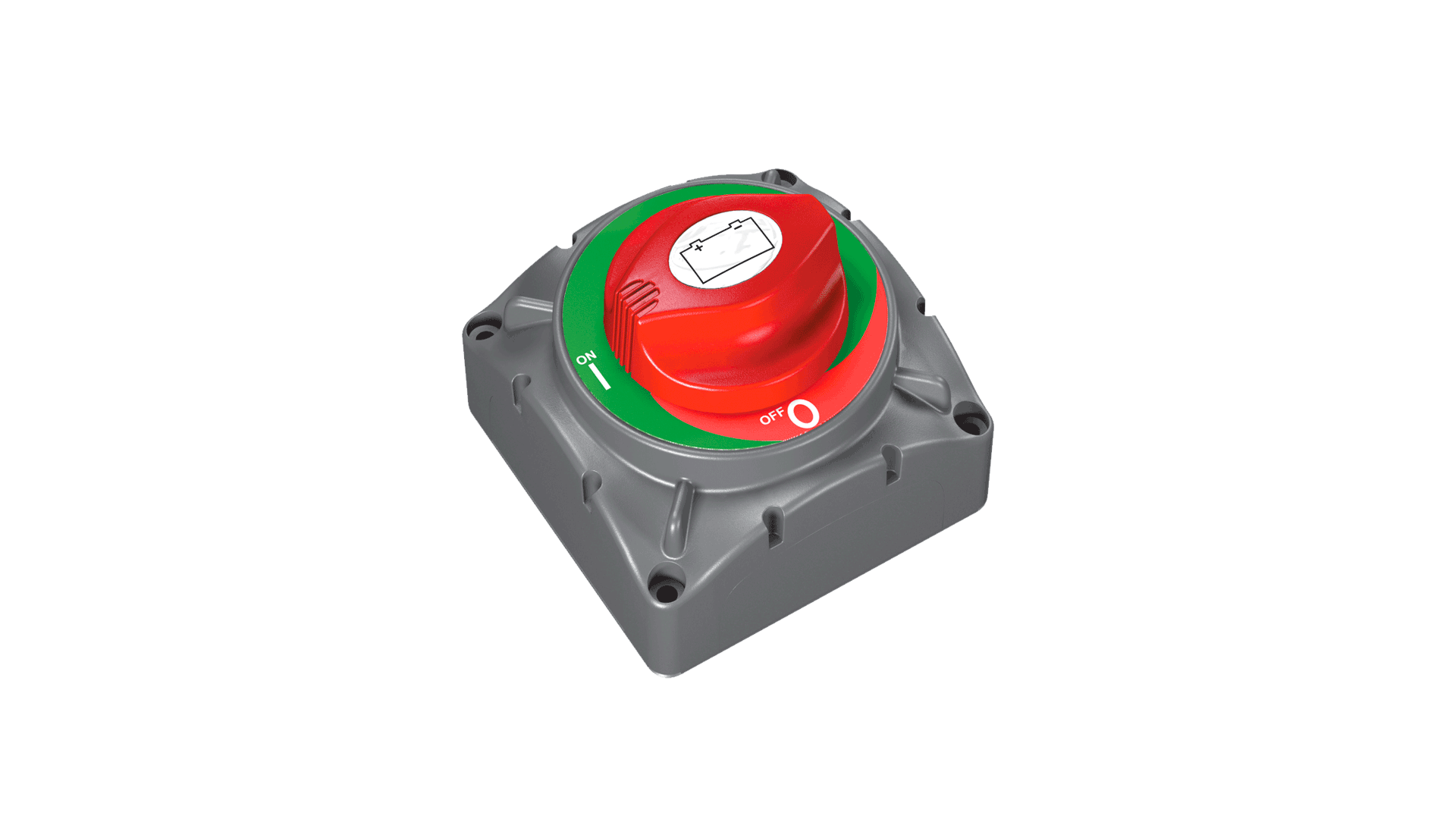
701 BATTERY SWITCH- 63142 C
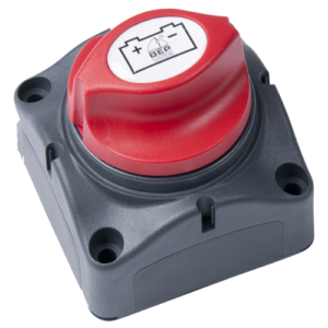
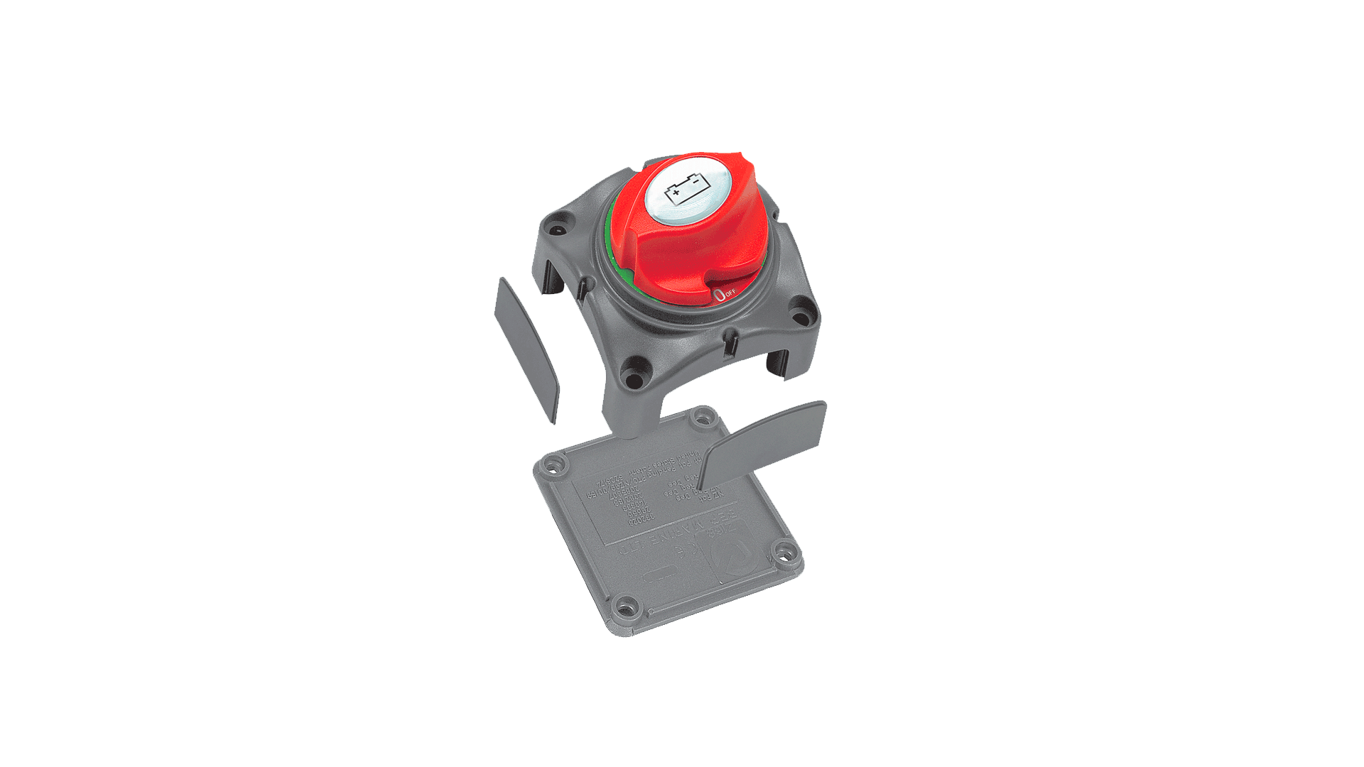
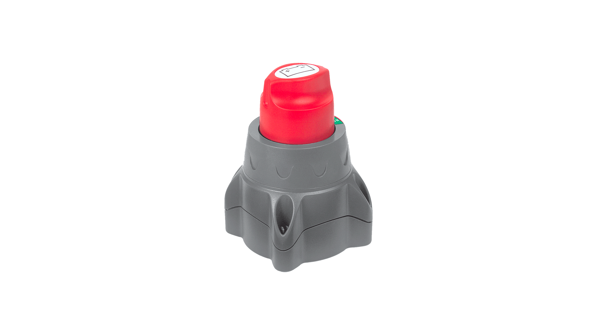
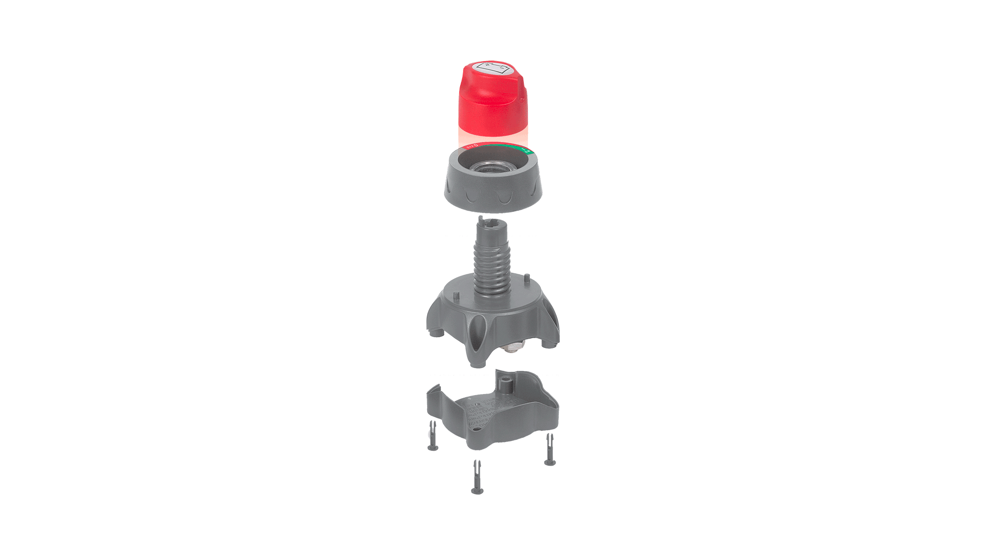
The 701 Contour Battery Master Switch offers a number of unique features. The highlights being the patented contour lock system, allowing it to be a stand alone unit, or locked together with other switches. The 701 also features a control knob which cannot be removed whilst in the On or OFF position, however can be removed by switching to an anti-clockwise 45° position. The control knob also features an interchangeable labelling system allowing a full range of applications (Set 715-713). The 701 also features removable side plates on 4 sides for access of up to 1/0 cables. Plus a rear cover insulating the rear terminals against any short circuits ensuring the switch meets ABYC requirements. The 701 can be either surface or recess mounted by cutting a 52 mm (2 1/16”) hole.
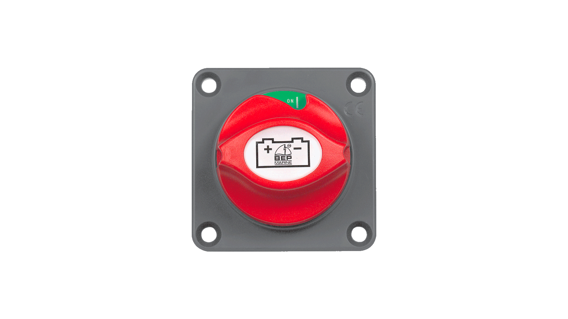
701-PM PANEL MOUNT BATTERY SWITCHES – 65494X
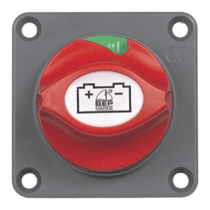
Same specifications as 701 switch
720 HEAVY DUTY BATTERY SWITCH – 63174S
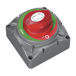
The 720 Heavy Duty Battery Switch fits into the same contour lock system as used on the battery distribution system. Rated at 600 Amp continuous and 2500 Amp cranking. It is well suited to larger vessels. As with the 701 and 720 can be recessed or surface mounted. The 720 uses the same style of self cleaning sliding contact as used in the 701. Also utilises the same label sheet as 701 (Set-715).
700 EASYFIT BATTERY SWITCH – 63672 J
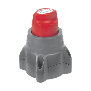
The 700 Easyfit is ideal on those installations where switches need to be recessed through varying thickness of panels. 700 Easyfit features an easily removable threaded ring allowing for panel thickness up to 19 mm (3/4”). It uses the same features as the 701 with the removable key 45° past the off position.
REPLACING KNOBS FOR 701 SWITCHES
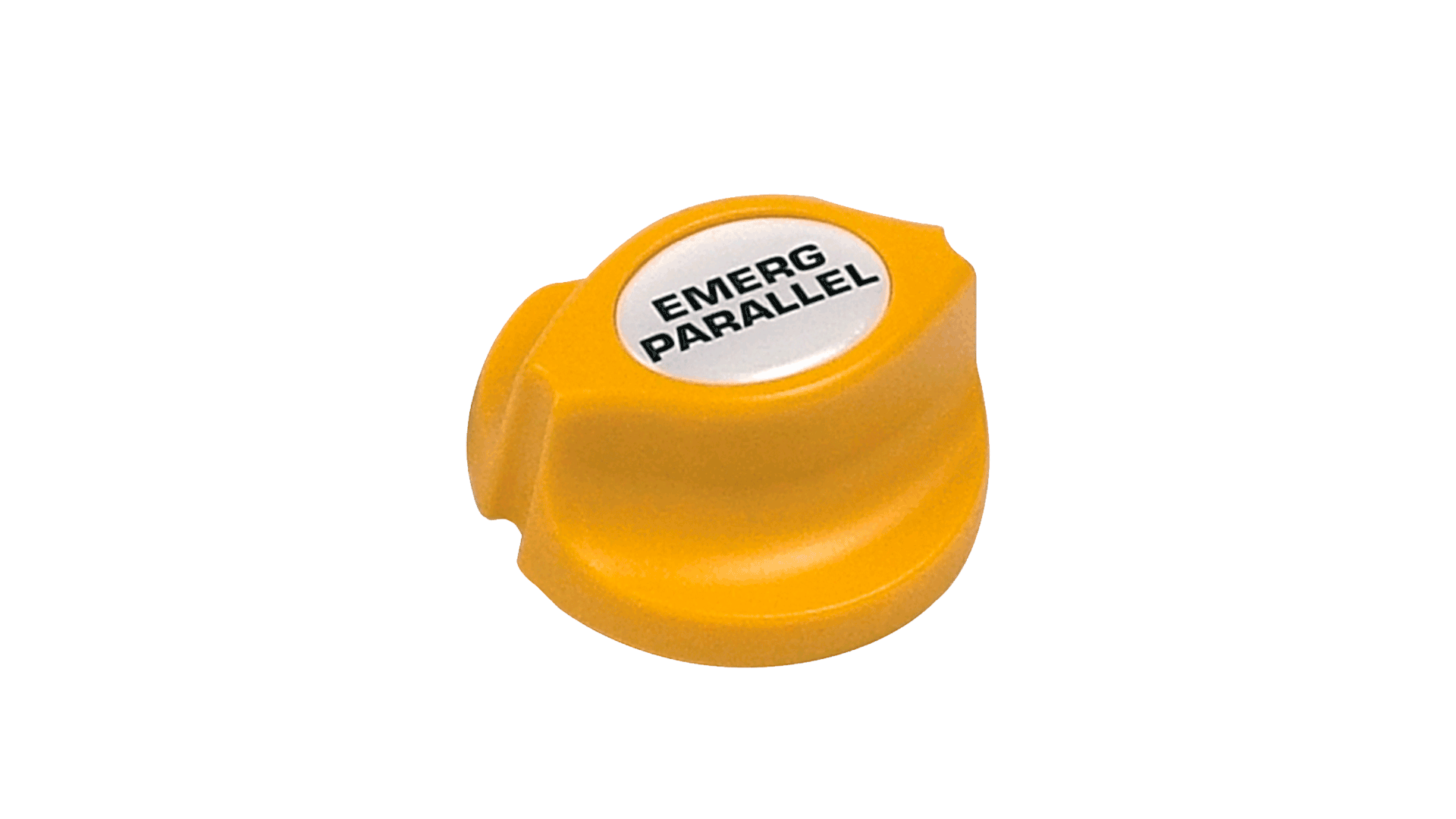
701-KEY-EP – 67866V replacing knob
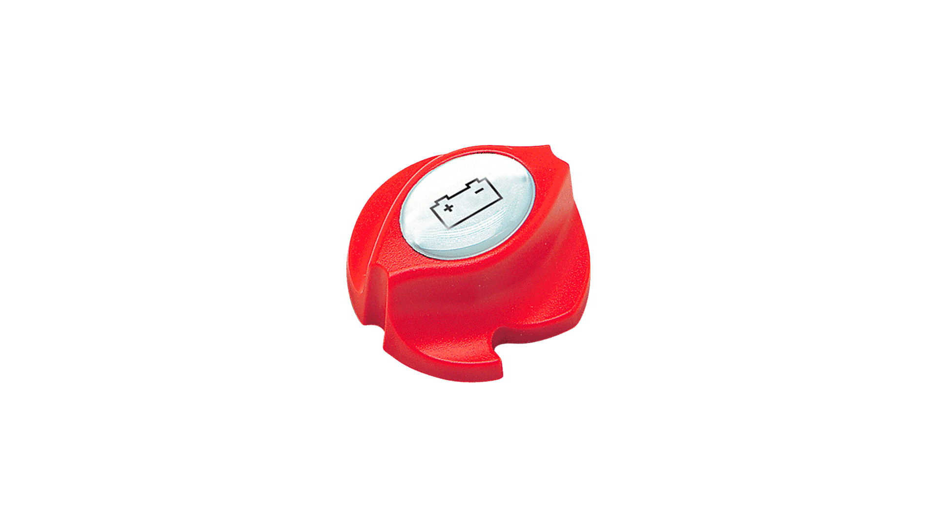
701-KEY – 63930E replacing knob
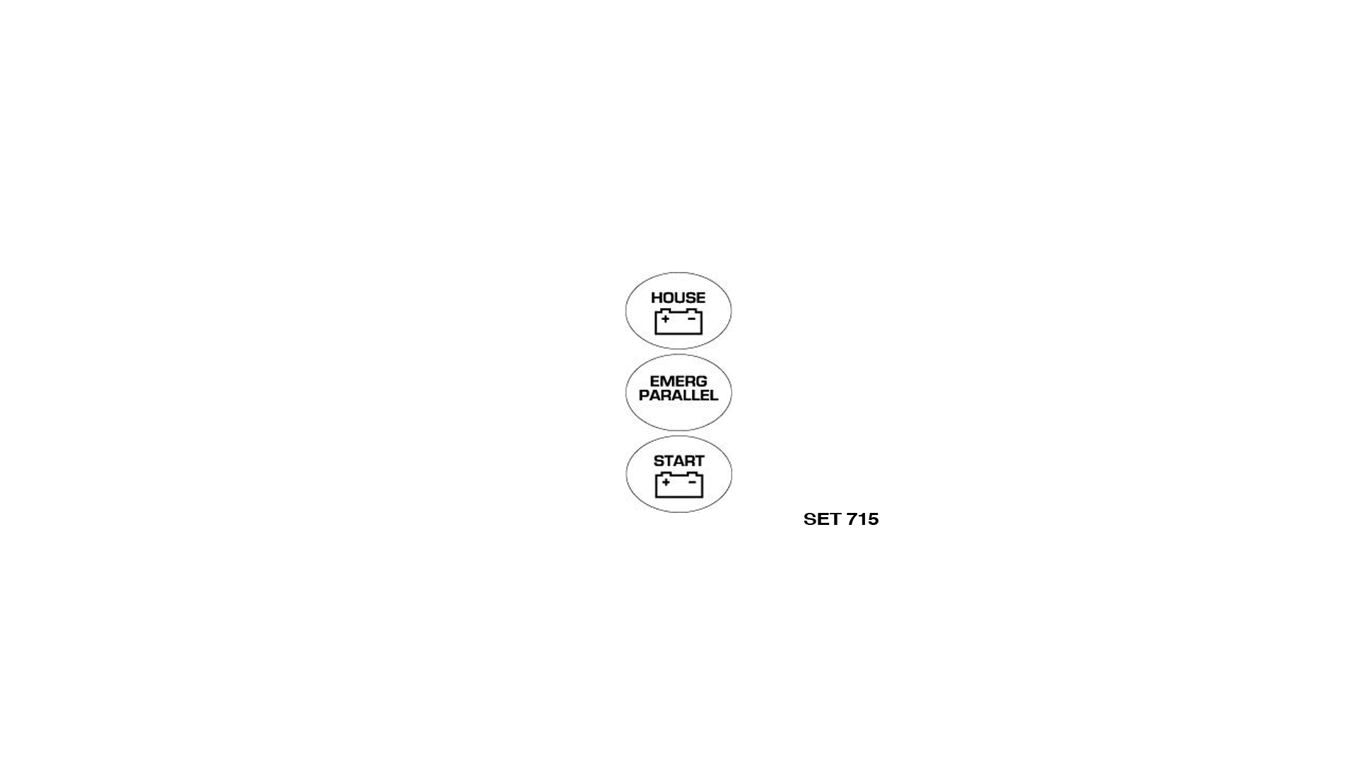
LABEL SET FOR BATTERY DISTRIBUTION SWITCHES
Set – 715 – 64389 V – Set 715 contains the three most commonly requested labels
BEP MARINE BATTERY SWITCH TEST PROCEDURES (UL 1107)
Continuous (1 hour) intermittent (5 minutes) and cranking (engine starting – 10 seconds). The test is to determine the maximum current the switch can handle for the stated time, without the rear terminals exceeding 100°C above the ambient temperature. The continuous and intermittent ratings are tested at 110% of specified ratings. All BEP switches are tested independently to this specification by a 3rd party laboratory.
